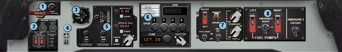
Lower Panel
| 1. Parking Brake/Warn | 2. Engine Start Panel | 3. Flaps Indicator | 4. Open/Hide Throttle and Compass Panels. |
| 5. Trim/Autopilot Controls | 6. Transponder/COM radio | 7. Power panel | 8. Fuel Control Panel |
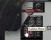
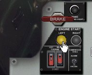
Engine Start
Procedure:
|
 |
 |
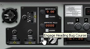
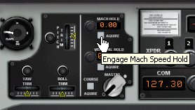
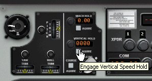
| This sector of the lower panel contains the electronic trim setting controls, and the autopilot functions for Mach speed hold, Vertical Speed Hold and Heading Hold. | |
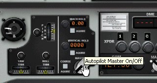 |
In order to function, both the avionics master switch and the AP/Trim Panel master switch must be ON. |
 |
 |
 |
|
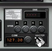
| This section of the
lower panel contains the Transponder, the COM radio, and the DME indicator
for the NAV radio.
The master power switch for this module must be turned ON, in addition to the master avionics switch on the power panel, in order for this instrument to operate! |
 |
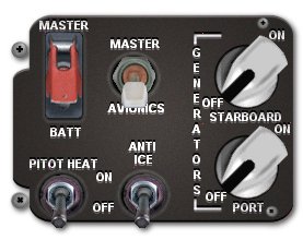 |
The power control
panel contains the Master Alt/Batt switch, as well as the Avionics Master
Switch.
Toggle switches for the pitot heater, anti-ice system, and the electrical generators for each engine are also located here. |
|
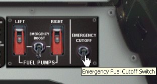
The fuel pump switches are located here, as well as the fuel booster pump system toggle, and the emergency fuel cutoff switch. The fuel pump switches must be on before attempting to start the engines! Engines can be stopped by shutting off the fuel pumps, or by using the emergency cutoff switch. |
 |
| Best viewed with: |
|
Results with obsolete browsers may vary
|
|
Copyright © 2002 by FSD International All rights Reserved
|