Cabin Pressurization/ECS
(Environmental Control System)
|
|
|
| The ECS system works in
conjunction with the cabin pressurization system to provide both safety and
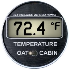
comfort to the crew and passengers. Always check the cabin temperature and cabin differential pressure periodically to insure that the proper comfort level is being maintained. Cabin temperature can be read on the OAT/Cabin Temp indicator on the main instrument panel. |
|
|
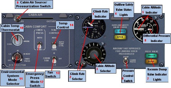
Use this knob to regulate the rate of change in the cabin pressure from a minimum of 175 FPM to a maximum of 2,500 FPM. |
|
The cabin altitude limit selector, in the center of the cabin pressure controller, is used to select the desired cabin altitude for cruise altitude. |
|
The outflow safety valve is mechanically the same as the isobaric valve. It differs in that it is not modulated by the cabin pressure, but rather, it is fully opened and closed. The safety valve opens during landing by the left gear squat switch action and stays open during ground operations to prevent pressurization of the cabin. It is held open during ground operations by vacuum supplied from the pneumatic system. |
|
Cabin pressure is monitored on the cabin altitude pressure gauge. This gauge is calibrated in feet. |
|
This switch controls the isobaric valve and mode of operation of the pressurization system. There are three positions:
|
|
This indicates the position of the outflow isobaric valve, which is a mechanical valve located on the upper aft pressure bulkhead. It is modulated by the cabin pressure controller to regulate the outflow of the pressurized cabin air so as to maintain the cabin altitude desired. When indicating Dump the valve is open to the outside atmosphere. When indicating Press the valve is modulated/regulated by the pressure control system. |
|
The difference in pressure between the outside atmosphere and the pressure vessel is monitored on the differential pressure gauge. This gauge is calibrated in pounds per square inch (PSI) pressure differential. |
|
Important note: the maximum allowable differential pressure within the pressure vessel is 7.6 PSI. While it is possible to maintain a very low cabin altitude at cruise altitudes above 15,000 feet, this will increase the differential pressure, thus putting strain on the outflow safety valve and the pressure seals throughout the pressure vessel, and causing discomfort to your passengers. A maximum differential pressure of between 6.0 - 6.4 PSI within the pressure vessel is recommended. |
|
Controls the air source for the cabin. When pressurization is desired, this selector must be set to Press. Otherwise the isobaric valve between the pressure vessel and the outside atmosphere will be open. |
|
Warning!: No cabin pressurization will occur if this selector is set to outside air source! |
|
Controls the comfort level of the cabin. Heating or coolant is applied to either outside air or pressurized cabin air. Works in conjunction with the ECS mode selector [11] and the Temperature Control Mode Selector [14]. |
|
Note: No cabin heating will be possible if the Temperature Control Mode Selector is set to Cool. Likewise, cooling will not be possible if the switch is set to Heat. In normal circumstances it is recommended that this switch be set to AUTO, which will allow for both heating and cooling, according to the Cabin Temperature Thermostat |
|
This is the main mode of control switch for the entire environmental/pressurization system. There are five (5) positions on this selector:
* If the Emergency Pressure Mode Switch [12] is set to manual (Man), rapid pressurization can only occur if the ECS Mode Selector is in Emer Press position. |
|
Warning!: No cabin pressurization will occur if this selector is set to OFF! |
|
Controls the Emergency Pressurization System (EPS). The EPS has two modes of operation:
|
|
Controls the rate of air circulation in the cabin. |
|
Controls the mode of operation (heating or cooling) of the ECS. There are three (3) modes of operation:
|
|
Copyright © 2003 by FSD International All rights Reserved. |